Light Gun Hacking Part 1: Using Namco light guns in Unity
There’s something very satisfying about holding an arcade light gun in your hands and having your ear drums shattered every time it recoils, that no other consumer or homebrew light gun has been able to replicate. The idea behind how a light gun works is quite simple: pull the trigger and the screen flashes white, if the light sensor detects light perform some calculations to figure out where on the screen the gun was aimed, if no light was detected then the gun missed the TV. But finding any technical details about how this calculation is performed, or how existing light guns work is not easy. I was able to find bits and pieces but nothing detailed enough that I could create my own light gun or modify an existing one for my needs. I wanted to be able to buy Namco arcade light guns online and use them on my PC or Xbox while hooked up to a CRT TV. In a previous experiment I wired up some Namco light guns up to an original Xbox and was able to play House of the Dead 2 and 3 with them. But the solution I came up with at the time was quite janky and required I mutilate a Xbox light gun controller as well. I wanted a more robust solution, one that would also let me connect the guns to my PC and allow me to make my own light gun shooter in Unity. My goals here are quite broad but they all centered around understanding how a light gun works under the hood. Once I had that knowledge it would be relatively easy to integrate them into Unity, Xbox, or another game console. In this post I’m going to cover how I reverse engineered the Namco light guns used in arcade games like Time Crisis 3, and was able to make my own Unity based shooting game using them. This post will be the first in a series of posts about reverse engineering light guns, understanding how they work, and eventually creating my own.
Initial investigation
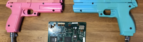
The light guns I had chosen to start with were the Namco light guns used in the arcade version of Time Crisis 3. Since I owned a Time Crisis 3 cabinet I had a working example to start with, and I quite liked the feel of these guns in particular. I should also mention that there are two different types of light guns used on Time Crisis 3, light based guns and IR based guns. The cabinet I had was light based so they had to be used on a CRT TV. Eventually I wanted to work with IR based ones but for now understanding how the light based ones worked would be a good starting point. The Time Crisis 3 cabinet is powered two Namco System 246 units which are actually PlayStation 2 consoles with an additional IO board that handles JVS (JAMMA Video Standard) signals. These signals include a 15kHz video feed that’s suitable for arcade CRT monitors, JVS IO which is used to talk to any input peripherals (light guns, steering wheels, instrument controllers, etc.), and a video sync signal that the light gun uses. The sync signal is a critical part of how these light guns work which I will go into detail on later in this post. Right now the important thing to determine is what type of sync signal is used: composite, V (vertical), or H+V (horizontal + vertical). The Namco light gun is connected to its own IO board which communicates over RS-485 to the System 246 unit using the JVS IO protocol. This IO board also handles the additional circuitry for the recoil circuit and sync signal processing, so being able to use the IO board would be ideal as I didn’t want to have to recreate this myself. The JVS IO protocol is pretty well documented and searching on the internet I found a number of projects on GitHub for communicating with JVS IO devices. Most of these projects were Arduino based and were used to connect JVS devices to PCs or connect keyboards/controllers to an arcade machine. One project in particular, OpenJVS, had a lot of information on the JVS protocol and hardware required to use it which was very helpful. This would be enough to get me started talking to the IO board but I still wanted to see what the light gun IO board was doing under the hood and how the game sending messages to it.
The TSS IO board
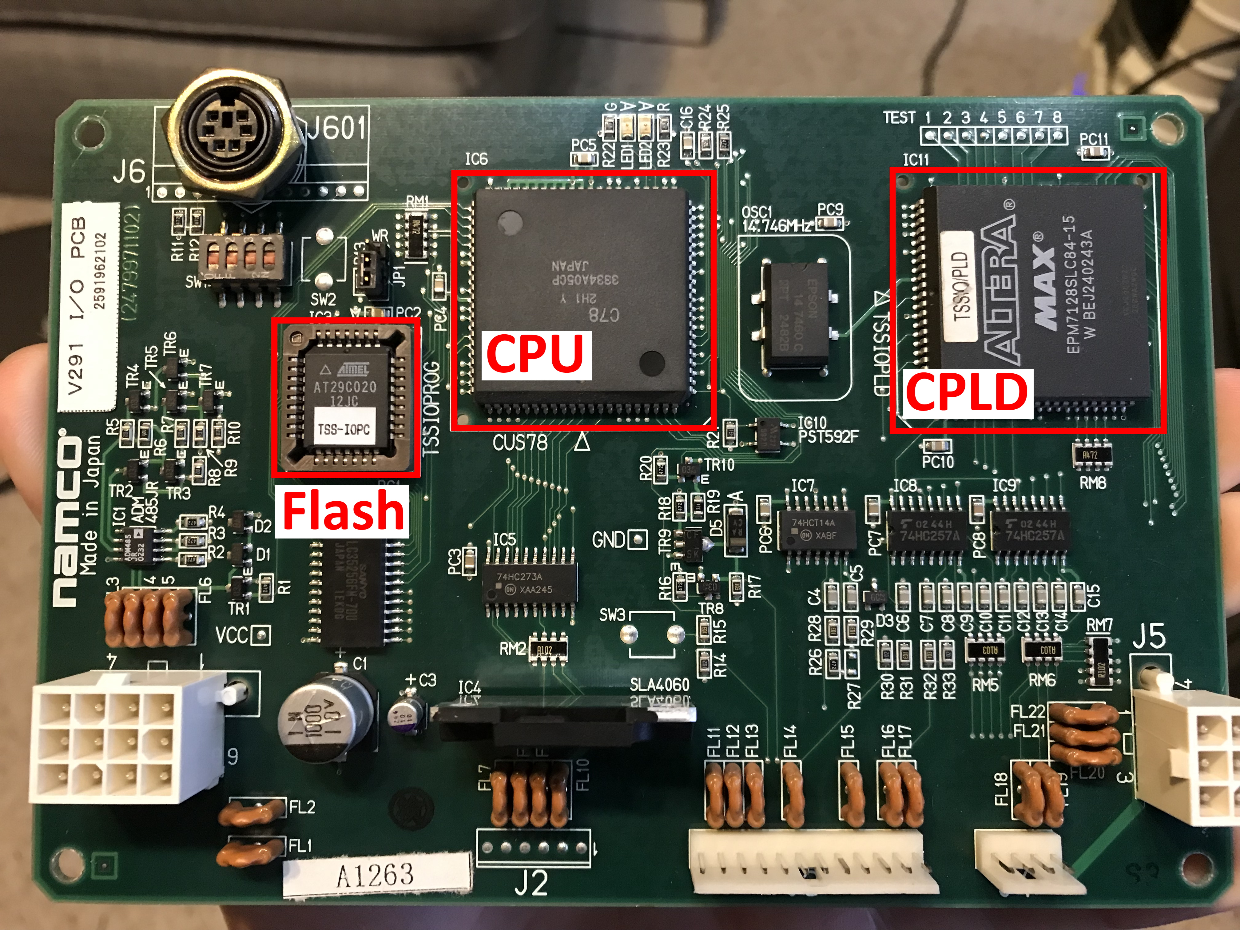
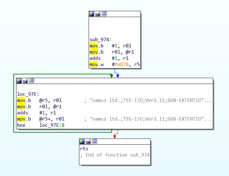
Taking a look at the IO board I saw it had an Altera CPLD, some unknown chip labeled “C78”, and a socketed PLCC32 flash chip. I suspected the CPLD was related to processing of the video sync signal, the C78 chip could be some sort of processor, and the flash chip would either have logic gate configurations for the CPLD or code for the processor. I popped the flash chip out of the IO board and put it into my chip programmer, and proceeded to dumped the contents. Looking at the flash dump in a hex editor I was able to see the JVS device ID string the board reports to the System 246 unit. The data looked to be code of some sort and I was able to determine it was big endian encoding, and even where some functions started and ended. But without knowing what architecture it was for I wasn’t going to get very far. My current theory was that this unknown C78 chip was a CPU chip but searching google I wasn’t really able to find anything on it. Eventually I was able to find a blog post by ‘Arbee’ that talks about the C78 chip being used on another IO board, and that it’s actually a Hitachi/Renesas H8/3334 CPU. Loading the flash dump in IDA with the processor type set to Hitachi H8/300 I was able to successfully analyze the code and it looked to be correct.
After a few hours of reverse engineering I had almost all of the 3kb of code reverse engineered. All the code related to the JVS communication protocol matched what I saw in OpenJVS (as expected), and I even figured out what some of the unknown Namco specific JVS commands did. I ended up reverse engineering so much of the code that I was able to map out what GPIO pins on the CPU are mapped to what memory addresses, and where a range of memory was mapped between the Altera CPLD and C78 CPU. At one point I actually tracked down a C compiler for this CPU on the Renesas website and thought it would be interesting to add some additional functionality to this IO board. But other than adding a button or two to the light gun (it normally has no additional buttons) I couldn’t think of anything worthwhile to add so I just shelved this idea for the time being.
While this research was interesting and it did help me get a better understanding of what the IO board was doing, it unfortunately didn’t help me learn anything new about the sync signal or coordinate data the light gun reports back to the System 246 for hit detection. The C78 CPU doesn’t actually handle the sync signal or coordinate data other than passing the coordinates it receives from the CPLD back over JVS IO. The CPLD doesn’t actually run code in the traditional sense but instead has a number of logical operations it can perform, so even if I had a way to dump this information out of the chip (which I didn’t), analyzing it would present a number of challenges. Since I pretty much learned everything I could from this IO board it was time to move on and start working on a setup for video feed and IO communication.
The JVS communication protocol
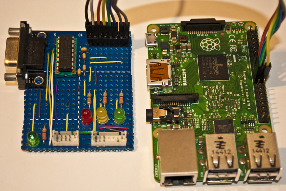
The first thing I needed to talk to the IO board was an RS-485 to usb adapter that I could use on my PC. If you’re not familiar with RS-485 it’s a variant of RS-232 but made for long distance communication (like multiple hundreds of meters). I had an adapter on hand and tried to use it but was getting nothing but comm errors when trying to send any data to the IO board. After a day of messing around with it I thought it might be broken and ordered another one on Amazon, only for it to arrive and give me the same results. I was pretty sure I had the A and B comm wires correct (I even verified this with info I found online), but on a whim I switched them around and it started working correctly (amateur mistake). Once that was working I wrote a bunch of code to send and received messages to the IO board so I could poll switch states, change GPIO states, and get coordinate data from the light gun. This let me map out exactly what switch states mapped to what buttons, and what GPIOs controlled things like the recoil on the light gun.
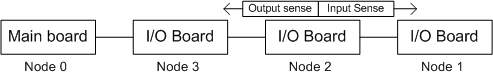
I’m not going to go too deep into the JVS communication protocol (PCB Otaku has some good information on it) but here is an overview of what it looks like. There’s a JVS master device (in this case the System 246 or my PC) which can communicate with up with 254 child devices. The child devices are chained together and have a “sense” line that’s used during device ID assignment to signal to other child devices that “I’m the one claiming this device ID”. During boot up the master device will send 2 reset messages and then assign device IDs to all child devices in the chain. After that it can send messages to any child device by including the child’s device ID in the message header. The master device is always device ID 0, and child devices can be from 1-254, with 255 being a broadcast address that all child devices will process.
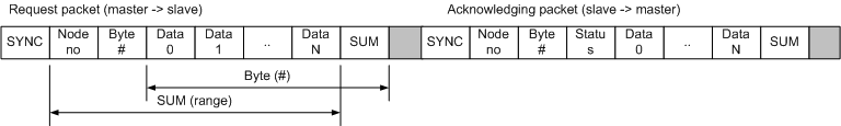
Every message is comprised of a synchronization byte (indicates the start of a message), the ID of the device the message is intended for, the message data being sent to/from the device, and a checksum byte to make sure the message transmitted successfully.
There are a number of commands that all JVS devices support and some that are “vendor” defined. Here is a list of some of the commands that can be sent:
- JVS
- RESET – Reset device state
- ASSIGN_ADDRESS – Assign a device ID to a child device
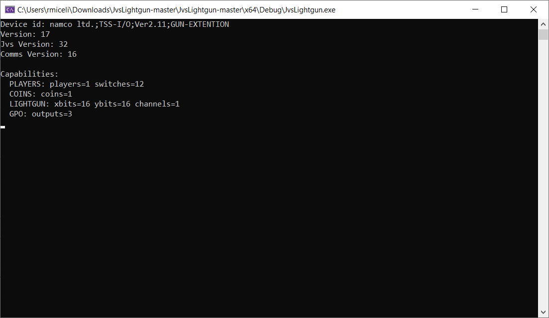
- REQUEST_ID – Requests a device ID string from the device, e.x.: ‘namco ltd.;TSS-I/O;Ver2.11;GUN-EXTENTION’
- GET_CAPABILITIES – Gets a list of capabilities the device supports (# of switches, GPIOs, coin slots, etc.)
- READ_SWITCHES – Gets switch states (what buttons are pressed)
- READ_COINS – Gets coin slot input state
- READ_GPIO – Reads the value of a GPIO
- WRITE_GPIO – Writes the value of a GPIO
- READ_LIGHTGUN – Gets hit coordinates for the light gun
- …
- Namco specific commands
- NAMCO_GET_POST_RESULT – Gets a power-on-self-test result for RAM integrity
- …
A single JVS message can contain multiple commands that will be processed by the child device and reply with a single message containing the result of each command in the same order they were received in. This helps to reduce transmission times since these messages are being sent and received every frame of the game. Time Crisis 3 typically sends the READ_SWITCHES, WRITE_GPIO, and READ_LIGHTGUN commands in a single message every frame to get the trigger state of the light gun, set the recoil GPIO (if it’s currently active), and get the hit coordinates of the gun. The game runs at 30fps so this round trip message is being processed every 33ms, so hardware handling this needs to be quite fast.
15kHz video signal hell
The next step was to get a suitable video signal from my PC that I could display on the arcade CRT and also split off the sync signal to feed into the IO board. The System 246 has a special IO board attached to the PS2 that has 2 VGA ports on it, one for video (15kHz RGBS) and one for the sync signal to the light gun IO board. Since the video out was using composite sync (horizontal and vertical sync muxed together) I figured the sync signal going to the IO board was also composite since there were only two wires being used. Just to verify, I probed the IO board sync signal and confirmed it was composite sync. Most arcade CRTs only work with 15kHz and/or 24kHz video signals, and the really good ones can auto detect the signal frequency and handle the switch between 15 and 24kHz accordingly. VGA output from a PC is 30kHz and is not compatible with old CRT screens. There are a few different video scalars you can use to convert a 30kHz signal down to 15kHz, but they are no longer made and highly sought after so I wasn’t able to find one. One such modern scalar that is supposed to do exactly this is the gbs-control. However, the gbs-control struggles with 30kHz input signals, and although I was able to get it work correctly exactly 1 time, I was never able to get it work again and decided to give up.
The next option was to use a (somewhat) older GPU that has DVI-A/DVI-I (DVI with analog signals) output along with a special hacked video driver called CRT EmuDriver, which would force the graphics card to output at whatever frequency I wanted. It seems this is what most people do when creating MAME cabinets using PCs, and supposedly it worked very well. But my PC is 20ft away from the arcade cabinet containing the CRT I wanted to display to which was not ideal. I tried to get a working eGPU setup with my MacBook which would make this all compact and portable, but after weeks of failed attempts I finally gave up, put the GPU in my desktop, and bought a 25ft VGA cable off Amazon.
I’ll spare you the details on all the struggles I went through trying to get the eGPU setup to work but there was one comical part that’s worth mentioning. Since I didn’t have a GPU with analog video out on hand I went to a local PC parts store to buy a used one for cheap. The first graphics card I picked out was quite dusty and while I was checking out the worker said he would dust it out for me. I thought great, now I don’t have to do it when I get home! I was expecting him to take the graphics card in the back or to some side room and use compressed air, but no. He proceeded to take the card outside the store, set it on the pavement, and dust it out using a leaf blower. I was going to stop him when I saw him about to put the card on the ground, but I remembered this card was only $60 and had a warranty, so I opted to see how this was going to play out and it was worth it. When he finished leaf blowing the graphics card he told me “it’s the best way”, to which I replied “cool”, and headed back home.
Anyways, after many failed attempts at the eGPU setup, I now had the GPU in my desktop with CRT EmuDriver setup and I was finally able to get working 15kHz video output to the arcade CRT. The next step was to split off the sync signal and feed it into the light gun IO board, but every time I connected it up the TV video feed would get distorted. The problem was that the signal was not strong enough to feed both the TV and the IO board at the same time (remember the System 246 has two VGA ports, this is why). So after ordering a powered VGA splitter off Amazon I was finally able to get working video and sync split. This entire part took over 4 weeks of trial and error before it finally worked, and was by far the hardest part of this entire process.
Powered by Unity
Now that I could talk to the light gun and get working video feed to the CRT it was finally time to start writing a Unity game to test this out top to bottom. I spent a couple hours Writing a sample Unity game that was basically a shooting range, it shows a crosshair on screen that moves with the mouse, and clicking would shoot a bullet and play a gun shot sound.
Once that was working smoothly I wrote a C# wrapper for the code I wrote to talk to the JVS IO board and imported it into Unity. Now I needed to change a few things up in order to make this test game compatible with the light gun. The first thing I had to do was implement a “flash frame” which would render the entire screen white for 1 frame when the trigger was pulled. This would be used to provide a light source for the light gun to detect and report back coordinates for where it saw the light. I couldn’t find any easy way to just clear the screen white in Unity, so I came up with a workaround which was to use a second camera out of view with the clear color set to white. When I wanted to render the flash frame I would just switch what camera was rendering to the screen for a single frame, and then switch back to the main camera on the next frame. It was janky but it worked.
|
1 2 3 4 5 6 7 8 9 |
void DrawFlashFrame() { // Set the flash camera as active. this.MainCamera.enabled = false; this.FlashFrameCamera.enabled = true; // Set the flash frame counter. this.flashFrameCounter = this.FlashFrameCount; } |
I would also need to cap the FPS to 30fps and enable vsync, which would make sure we match the refresh rate of the screen and only draw frames on sync intervals. If vsync is not enabled screen tearing could prevent parts of the screen from showing as white, and if we don’t limit the fps we could draw frames faster than the TV can display them and actually miss a flash frame entirely. By limiting fps and setting vsync we (in theory) limit the game to drawing frames at the same rate as the TV and prevent these issues.
Next I needed to get the coordinates reported by the light gun and transform them into screen coordinates. The coordinates the light gun reports are in terms of it’s own coordinate space. In order to use them in Unity I would first have to translate them into Windows screen coordinates (where on the monitor did the light gun hit), then translate those into world space coordinates (a position in the 3d game world), and finally I could raycast into the 3d world to actually fire the bullet. While this sounds complicated it is actually pretty simple. First we take the coordinates reported by the gun and adjust them for the calibration offset, this corrects the coordinates for adjustments in how the video is being displayed, e.x.: if the video is shifted to the right/left/top/bottom the light gun coordinates will be off. Then we transform the light gun coordinates into Windows screen coordinates using a ratio of light gun screen size to game window screen size. To figure out the light gun screen bounds I went into the service menu on the Time Crisis 3 cabinet and pulled up the gun calibration screen. This screen lets you shoot around and draws a cross where the gun was aimed when shot. While I was shooting around the screen I was also sniffing the JVS IO traffic and was able to see the coordinates returned when I shot the 4 corners of the screen. With this I can now transform the light gun coordinates into 3d world coordinates even without really understanding how the light gun calculates the coordinates to begin with.
|
1 2 3 4 5 6 7 8 9 10 11 12 13 14 |
// Get the game window information. System.Type T = System.Type.GetType("UnityEditor.GameView,UnityEditor"); EditorWindow gameview = EditorWindow.GetWindow(T); Vector2 screenSize = gameview.position.size; // Adjust the lightgun coordinates by the offset at which the screen is visible. Vector2 gunPos = this.LightgunPostion - this.GunScreenOffset; // Unity (more like Windows) coordinates have (0, 0) in the bottom left, TSS IO has (0, 0) in the upper left. Flip // the y coordinate from TSS IO coordinate grid to Unity coordinate grid. gunPos.y = this.GunScreenSize.y - gunPos.y; // Transform the lightgun coordinate to a screen coordinate. Vector2 temp = (gunPos / this.GunScreenSize) * screenSize; |
Once we have the screen coordinates we can transform these into a position in the 3d world using the camera transform matrix. When you want to take a 3d point in the world and project it onto your 2d computer screen you transform the 3d point by the camera transformation matrix, which quite literally transforms a 3d point in world space into a 2d point in screen space. To do the reverse and project a screen coordinate into the 3d world you transform the screen coordinate by the inverse camera transformation matrix (basically doing the opposite transformation). Unity wraps this into a simple API so you don’t need to understand any of this:
|
1 |
Vector3 hitPos = this.MainCamera.ScreenToWorldPoint(new Vector3(temp.x, temp.y, 2f)); |
Now we have the 3d world position of where the gun was fired from. Normally you would ray cast into the world and check if it hit an enemy, but for this test game we’re just going to draw a bullet hole at this 3d position without ray casting into the world. The last thing to do was change the render loop to check if the gun trigger was pressed, draw a flash frame, and then check if the light gun hit the screen. The final logic looks like this:
|
1 2 3 4 5 6 7 8 9 10 11 12 13 14 15 16 17 18 19 20 21 22 23 24 25 26 27 28 29 30 31 32 33 34 35 36 37 38 39 40 41 42 43 44 45 46 47 48 49 50 51 52 53 54 55 56 57 58 59 60 61 |
// Update is called once per frame void Update() { // Check if lightgun flash is still active. if (this.flashFrameCounter > 0) { // Update frame counter. this.flashFrameCounter--; // If flash frame counter reaches 0 set the main camera as active. if (this.flashFrameCounter == 0) { this.MainCamera.enabled = true; this.FlashFrameCamera.enabled = false; } // Check if the bullet hit the screen. if (this.lightgun != null && this.lightgun.LightgunPostion.x != 0f && this.lightgun.LightgunPostion.y != 0f) { // Place the bullet on the screen. FireBullet(this.lightgun.LightgunScreenPosition); // Fire recoil. this.lightgun.ToggleRecoil(RecoilType.Active3Supress3); } } // Check for fire action. if (Input.GetMouseButtonDown(0) == true) { // Draw bullet on screen. FireBullet(new Vector2(Input.mousePosition.x, Input.mousePosition.y)); } else if (this.lightgun != null && this.lightgun.GetSwitchState(LightgunButton.GunTrigger) == true && this.previousLightgunState == false) { // Set the lightgun state. this.previousLightgunState = true; // Draw the flash frame. DrawFlashFrame(); } else if (this.lightgun != null && this.lightgun.GetSwitchState(LightgunButton.GunTrigger) == false) { // Reset lightgun trigger state. this.previousLightgunState = false; } // Only draw the crosshair when the flash frame isn't active. if (this.flashFrameCounter == 0) { // If the lightgun is enabled use it's coordinates to place the crosshair, otherwise use the mouse. if (this.lightgun.Enabled == true && this.lightgun.Connected == true) { this.CrosshairObject.transform.position = new Vector3(this.lightgun.LightgunScreenPosition.x, this.lightgun.LightgunScreenPosition.y, 0f); } else { this.CrosshairObject.transform.position = Input.mousePosition; } } } |
The final result
With these changes in place I was able to aim the light gun at the screen and see the crosshair move around where I was pointing. Pulling the trigger would place a bullet hole on screen and fire the recoil on the gun. The Unity test game was working great and it was quite satisfying to see this come together. But there were a couple issues I still needed to work out at a later time. The first and biggest issue was that the USB to RS-485 adapter I was using was not able to communicate at a fast enough pace for what I needed. Time Crisis 3 was polling the IO board every frame so it was able to process a round-trip message (send and receive reply) every 1 second / 30fps = 64ms. I was only able to do this a few times per second and the adapter would periodically throw IO errors in the process, dropping whatever message was being sent or received. It was so bad I actually had to create a background thread that would just continuously poll the IO board state and report the status asynchronously so that I wouldn’t kill FPS on the main thread. This also made it very difficult to create a recoil that didn’t feel sloppy. The recoil mechanism works by toggling a GPIO that activates the slide solenoid on the gun. Pulling it high activates the solenoid and pushes the slide back, pulling it low releases the solenoid and the slide resets. As long as the GPIO is pulled high the solenoid stays activated. This lets you create different recoil effects depending on how long you keep the GPIO pulled high, which is what Time Crisis 3 does to create different recoil effects for each of the 4 guns in the game. But because this RS-485 adapter could only be polled a few times per second I wasn’t able to get a recoil that felt consistently good, sometimes it would fire just right, and other times it was too long and felt “sloppy”. I’ll eventually fix this later by ditching the RS-485 adapter in place of something better suited for fast polling.
The second issue was that I didn’t have a calibration screen implemented yet so I had to offset the light gun coordinates by a static calibration offset. This worked for my screen but I want to eventually implement a calibration screen to make using this on any screen easier.
The full source code and unity project can be found on my Github: UnityJVSLightgun
So how EXACTLY does the light gun work?
Now that the light gun is working in Unity lets dive into how exactly the Namco TSS light gun works. Earlier in the post I talked about needing to split the sync signal off of the video output from my PC to feed it to the IO board, but didn’t go into detail about what this signal is or why it’s needed. In order to understand how the sync signal works you’ll need to understand how a CRT television draws an image on screen. If you’re already familiar with this process feel free to skip over this next section.
Drawing an image on a CRT TV
Inside of a CRT TV is an electron gun (there’s actually 3 of them, one for each color) that fires a very fine beam of charged electrons at the screen. The screen is coated with phosphors and when the electrons hit the phosphors they emit a light which is what you end up seeing. To fill the screen with an image the electron gun moves from left to right, top to bottom, firing electrons at the screen to light up the phosphors for each “pixel” in the image. This happens at an extremely fast rate, in our case the screen is refreshing at 30Hz so 30 images are drawn every second (it’s actually drawing 2 half images every frame for a total of 60 half images per second because the video is interlaced). The human eye can’t tell it’s happening, but if you record a CRT TV with a high frame rate camera and slow it down you can actually see the electron beam move across the screen as an image is drawn:
The TV can display a variety of video signals (VGA, composite, component, S-video, etc.) but the one we’re going to focus on is VGA since that’s what we’re driving the CRT with. VGA has 3 signals for Red, Green, and Blue, and then 1 or 2 additional signals for sync depending on if you’re using RGBHV (horizontal + vertical) or RGBS (composite sync: horizontal and vertical sync combined into one signal). These signals are what “drive” the CRT gun as it moves around the screen and lights up the phosphors. Horizontal sync is used to move the gun to the next horizontal line and vertical sync is used to move the gun back to the top of the screen. The sync signals don’t allow you to “move 3 pixels to the right on line 7”, only “start a new horizontal line” and “move back to the top”. As the gun moves from left to right for a single line it uses the RGB signals (along with witchcraft) to light up the phosphors the correct colors. This happens at an extremely fast rate, for a 15kHz 640x480i 30Hz signal the CRT gun is drawing 1 horizontal line every 63.5us. Now you might be saying “but wait, 1 second / 30 fps / 480 lines does not equal 63.5us it’s 69us!”, and yes you’re correct. That’s because the TV is not drawing 480 lines it’s actually drawing 525 lines. These extra lines are not visible on screen are used for field synchronization (used in interlaced video modes), wait time for the electron gun to move back to the top of the screen, signal quality information (used to determine signal quality from the TV broadcasting station), and information for closed captions. I have no idea what information these lines contain for game consoles, but my guess is they are just “empty”.
The IO board sync signal
The System 246 outputs RGBS (composite sync) so the IO board is receiving both horizontal and vertical sync in a single signal. I probed the sync signal going to the IO board and if we look at it side by side with the signal spec for NTSC 480i composite video we can see they match up nicely:
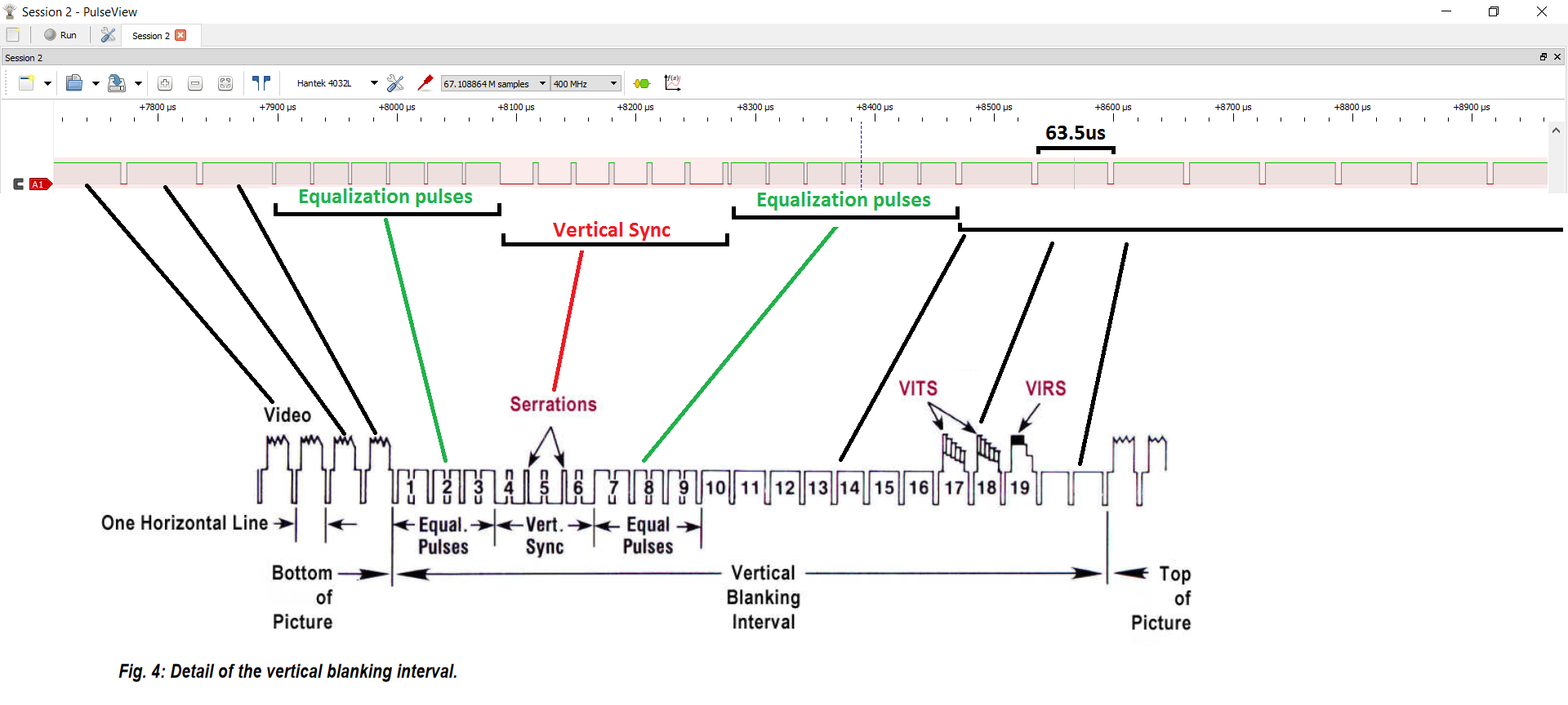
Now that we understand how a CRT draws an image to the screen and what this sync signal looks like we can piece together how the light gun figures out where on the screen it was aimed when it saw light. The IO board can watch the sync signal for the start of a new frame which is indicated by the vertical blanking interval. Once the new frame starts it can track the vertical position by counting the horizontal sync pulses which indicate which line is being draw. When the light sensor detects light the IO board can calculate the horizontal position by tracking how much time elapsed between the start of the horizontal sync pulse and when light was detected. The CPLD on the IO board probably can’t track time this fast but it can figure out the starting time for the current line by multiplying the horizontal line number by the time it takes to draw a single line. For example, if we know that a single horizontal line takes 63.5us to draw and light was observed 20us after the start of the sync pulse for line 30, we can calculate the horizontal pixel position like so:
|
1 2 3 4 5 6 |
totalTimeH = 63.5; horizontalLineCount = ...; // 30 elapsedTime = get_time(); // 20us into the current line timeInCurrentLine = elapsedTime - (horizontalLineCount * totalTimeH); // 20us horizontalPos = (timeInCurrentLine / totalTimeH ) * 640; // = 202 |
Calculating screen coordinates
A more complete implementation that handles vertical blanking and full position calculation would probably look something like this (note: this is untested code):
|
1 2 3 4 5 6 7 8 9 10 11 12 13 14 15 16 17 18 19 20 21 22 23 24 25 26 27 28 29 30 31 32 33 34 35 36 37 38 39 40 41 42 43 44 45 46 47 48 49 50 51 52 53 54 55 56 57 58 59 60 61 62 63 64 65 66 67 68 69 70 71 72 73 74 75 76 77 78 79 80 81 82 83 84 85 86 |
const unsigned int screenWidth = 640; const unsigned int syncThreshold = 63.5us / 2; byte vblankPeriod = 0; byte lightDetected = 0; unsigned long hsyncTime0 = 0; unsigned long hsyncTime1 = 0; unsigned int hLine = 0; unsigned int posX = 0; unsigned int posY = 0; // Sync interrupt triggered on falling edge void on_sync() { // Save the interrupt time and check if this was a short pulse (indicates vblank period). hsyncTime0 = hsyncTime1; hsyncTime1 = get_time(); if (hsyncTime1 - hsyncTime0 < syncThreshold) { // Vertical blanking period detected, skip the next 21 pulses. hLine = 0; vblankPeriod = 1; } // Increment the line counter. hLine++; // Check if the vertical blanking period is complete. if (vblankPeriod == 1 && hLine == 22) { // Vertical blanking period complete. vblankPeriod = 0; hLine = 0; // If light was detected wait 1 frame before clearing the hit position. if (lightDetected == 1) lightDetected = 0; else { // Reset hit position. posX = 0; posY = 0; } } } // Ligth detect interrupt triggered on rising edge void on_light_detect() { // Get the current time and line count. We get the time first because if time is off the hit position will // dift to the right whereas if the line count is off we can detect this below and compensate. unsigned long time = get_time(); posY = hLine; // Calculate the horizontal position using the time the interrupt was fired and starting time of the // current horizontal line. unsigned long startTime = 63.5us * posY; if (startTime > time) { // The line count changed asynchronously, adjust it until we find the correct horizontal line. unsigned int i = 1; for (; i <= 3; i++) { if (63.5us * (posY - i) < time) break; } // If we couldn't find the correct horizontal line after 3 attempts something is wrong and we should bail out. if (i == 3) { posY = 0; posX = 0; return; } startTime = 63.5us * (posY - i); } posX = ((time - startTime) / 63.5us) * screenWidth; // Flag that light was detected. lightDetected = 1; } |
Since this code needs to run very fast in order to handle the 63.5us sync pulses the H8/3334 CPU on the light gun IO board is simply not up to the task. This is what the Altera CPLD is for, it handles the light detection logic and reports the calculated hit coordinates back to the CPU. I haven’t figured out exactly how this happens but there is a range of memory that is mapped between the H8/3334 CPU and the Altera CPLD, so it may that the some of the lines from the CPLD are connected directly to the CPU memory mapped IO ports.
The entire process start to finish
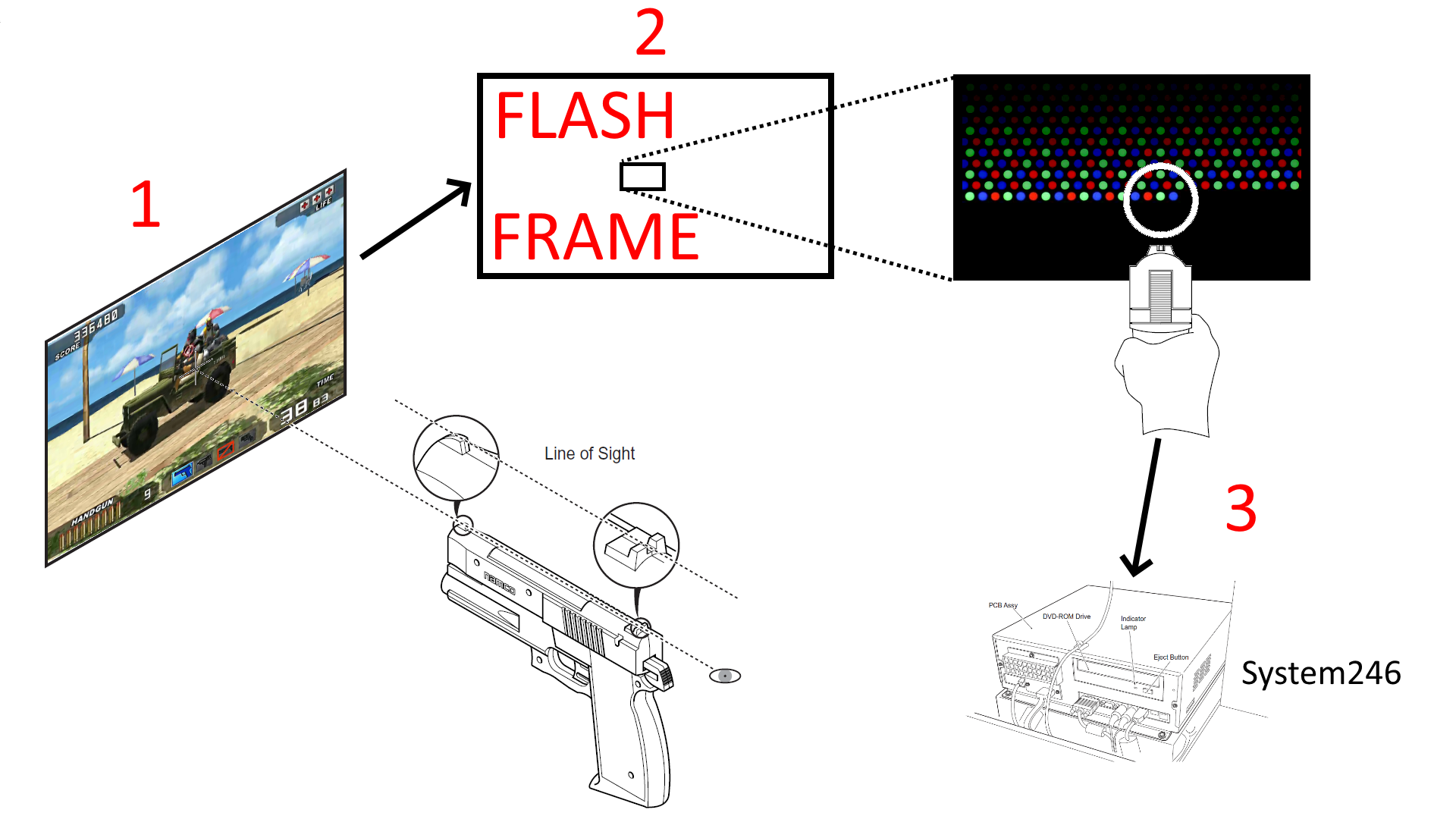
Now that we understand how the light detection works lets take a look at the entire process from start to finish. While the player is playing the game they press the gun trigger to fire a bullet and the follow events happen:
- The player presses the gun trigger, the game detects this and draws a flash frame (clears the entire screen to white) to make sure the screen is as bright as possible for the light sensor to detect.
- During the flash frame the Altera CPLD on the IO board will watch the sync signal and when light is detected it will calculate the screen position based on the current line counters, and report this position back to the H8 CPU.
- Note: The IO board runs asynchronously from the System 246 so it has no concept of what frames are flash frames vs normal game frames. It will report coordinates back to the CPU if light is detected regardless of frame type, and in my tests if the screen frame is at 50% brightness or higher it will detect light. If the game you’re playing is well lit you could probably draw a crosshair on the screen using the light gun coordinates and it would work just fine, but if you’re playing a dark game (such as a horror game) you will most definitely need the flash frames.
- After the flash frame the game will poll the IO board status and get the hit position for where light was detected on screen, transform the light gun coordinates into game world coordinates, and raycast to simulate gun fire.
And that’s how the Namco light gun works. With this information I can easily adapt this gun to work on an Xbox console. Of course I won’t be able to use the IO board as-is because the Xbox uses different video signals for light gun processing. But now that I understand how to use the video signals to calculate where on the screen the gun observed light I can easily program a micro controller to do this for the Xbox video signals.
Conclusion
Excluding the numerous setbacks I encountered with RS-485 dongles, 15kHz video feeds, and sync signals, this project was a lot of fun and I learned a lot about how light guns work and how various video signals are displayed on screen. With the information I learned I can now make my own light gun game in Unity, and have already begun working on adapting the Namco light gun to Xbox so that it can be used as a light gun controller with House of the Dead (plus an additional secret project). The next post in this series will most likely cover that, and eventually I want to try making an IR based light gun to work on modern TVs and monitors.
All of the code for the Unity project and JVS communication can be found on my Github: UnityJVSLightgun, so if you’re interested in trying to recreate this process go check it out. I will give a word of warning though, unless you have a strong desire to use a CRT TV and don’t want to mount IR emitters, an IR gun is absolutely the way to go. Not only can it work on any screen type of any size, it also doesn’t require any information from the video feed or special hardware so you don’t need to go through the trouble I did trying to get this setup. Also if anyone is looking to purchase a Time Crisis 3 DX cabinet let me know, I plan to sell this thing off pretty soon…